SCHEMI DI INSTALLAZIONE
INSTALLATION DIAGRAM
La scelta dello schema di installazione deriva spesso da un compro-
messo tra diverse esigenze, che riguardano principalmente l’efficien-
za energetica e la semplicità di messa in opera.
Sono possibili due diverse disposizioni del recuperatore, descritte
nelle seguenti figure - gli utilizzi sono schematizzati da un solo punto
di prelievo, ma è possibile che gli utilizzi siano più d’uno.
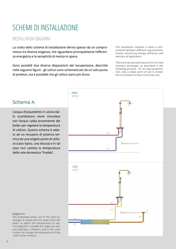
Schema A
The installation network is often a com-
promise between different requirements,
mainly concerning energy efficiency and
easiness of application.
There are two possible layouts for the heat
recovery exchanger, as described in the
following pictures - for an easy presenta-
tion, only a single point of use is shown,
but no problem to have more than one.
PRIMA
BEFORE
50°C
10°C
38°C
L’acqua d’acquedotto in uscita dal-
lo scambiatore viene miscelata
con l’acqua calda proveniente dal
boiler per regolare la temperatura
di utilizzo. Questo schema è adat-
to ad un recupero di potenza ter-
mica da una singolo punto di utiliz-
zo (caso tipico, una doccia) e in tal
caso non cambia la temperatura
della rete domestica “fredda”.
6
Diagram A
The preheated water out of the heat ex-
changer is mixed with hot water from the
boiler to adjust the temperature of use.
This diagram is suitable for single use out-
put (typically, a shower), and in this case
it does not change the temperature of the
“cold” home network.
DOPO
AFTER

