EFFEBI-PRESS
- lasciare gli spazi sufficienti per la dilatazione;
- utilizzare i compensatori di dilatazione;
- disporre correttamente sia i collari fissi che quelli scorrevoli.
Per calcolare la dilatazione longitudinale, si deve usare la
seguente formula:
∆L = α • L • ∆T / 1.000
dove:
∆L è la dilatazione in mm;
α è il coefficiente di dilatazione del materiale espresso in
mm/m • °C;
L è la lunghezza della tubazione in m;
∆T è lo sbalzo termico in gradi ammissibile.
La tab. 7 indica i coe
fficienti di dilatazione per i diversi materiali
delle tubazioni.
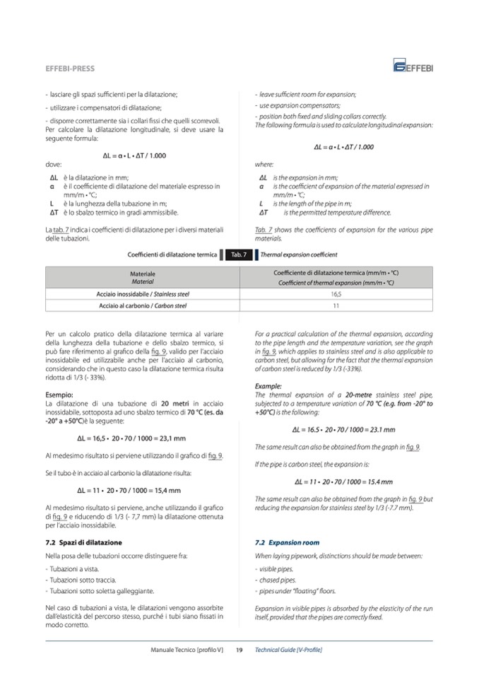
Coefficienti di dilatazione termica
Per un calcolo pratico della dilatazione termica al variare
della lunghezza della tubazione e dello sbalzo termico, si
può fare riferimento al grafico della fig. 9, valido per l’acciaio
inossidabile ed utilizzabile anche per l’acciaio al carbonio,
considerando che in questo caso la dilatazione termica risulta
ridotta di 1/3 (- 33%).
Esempio:
La dilatazione di una tubazione di 20 metri in acciaio
inossidabile, sottoposta ad uno sbalzo termico di 70 °C (es. da
-20° a +50°C)è la seguente:
∆L = 16,5 • 20 • 70 / 1000 = 23,1 mm
Al medesimo risultato si perviene utilizzando il grafico di fig. 9.
Se il tubo è in acciaio al carbonio la dilatazione risulta:
∆L = 11 • 20 • 70 / 1000 = 15,4 mm
Al medesimo risultato si perviene, anche utilizzando il grafico
di fig. 9 e riducendo di 1/3 (- 7,7 mm) la dilatazione ottenuta
per l’acciaio inossidabile.
7.2 Spazi di dilatazione
Nella posa delle tubazioni occorre distinguere fra:
- Tubazioni a vista.
- Tubazioni sotto traccia.
- Tubazioni sotto soletta galleggiante.
Nel caso di tubazioni a vista, le dilatazioni vengono assorbite
dall’elasticità del percorso stesso, purché i tubi siano fissati in
modo corretto.
Tab. 7
- leave sufficient room for expansion;
- use expansion compensators;
- position both fixed and sliding collars correctly.
The following formula is used to calculate longitudinal expansion:
∆L = α • L • ∆T / 1.000
where:
∆L is the expansion in mm;
α is the coefficient of expansion of the material expressed in
mm/m • °C;
L is the length of the pipe in m;
∆T
is the permitted temperature difference.
Tab. 7 shows the coefficients of expansion for the various pipe
materials.
Thermal expansion coefficient
For a practical calculation of the thermal expansion, according
to the pipe length and the temperature variation, see the graph
in fig. 9, which applies to stainless steel and is also applicable to
carbon steel, but allowing for the fact that the thermal expansion
of carbon steel is reduced by 1/3 (-33%).
Example:
The thermal expansion of a 20-metre stainless steel pipe,
subjected to a temperature variation of 70 °C (e.g. from -20° to
+50°C) is the following:
∆L = 16.5 • 20 • 70 / 1000 = 23.1 mm
The same result can also be obtained from the graph in fig. 9.
If the pipe is carbon steel, the expansion is:
∆L = 11 • 20 • 70 / 1000 = 15.4 mm
The same result can also be obtained from the graph in fig. 9 but
reducing the expansion for stainless steel by 1/3 (-7.7 mm).
7.2 Expansion room
When laying pipework, distinctions should be made between:
- visible pipes.
- chased pipes.
- pipes under “floating” floors.
Expansion in visible pipes is absorbed by the elasticity of the run
itself, provided that the pipes are correctly fixed.
Materiale
Material
Coefficiente di dilatazione termica (mm/m • °C)
Coefficient of thermal expansion (mm/m • °C)
Acciaio inossidabile / Stainless steel
16,5
Acciaio al carbonio / Carbon steel
11
Manuale Tecnico [profilo V]
19
Technical Guide [V-Profile]

