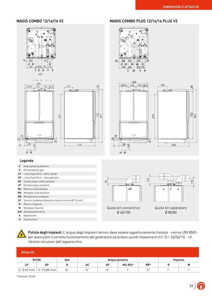
MAGIS COMBO 12/14/16 V2
MAGIS COMBO PLUS 12/14/16 PLUS V2
40
50 35
35
35
LP GP
RU MU SC
40
50 35
35
135 60
55 70
35
LP GP
RU MU SC
G
RR
R M
135 604405570
137
8
2
139.5G11R5R 11R57M0.5
137
2
8
440
137
8
8
139.5 115
115 70.5
137
2
2
9
7
2
7
1
8
9
2
1
6
7
6
7
1
8
9
7
2
7
1
8
9
7
2
7
1
8
6
6
4
0
50
35
LP GP
SC
135 4550 90 70
4
0
50
35
G AC AF R M
LP GP
440
SC
135 4550 90 70
139.5 115 115 70.5
G AC AF R M
* Versioni PLUS
440
139.5 115
115 70.5
5
0
1
0
1
2
7
4
5
2
7
4
V
0
9
0
35
474
5
1
5
6
1
6
1
9
2
7
4
2
1
7
4
V
35
LP GP
V
35
9
9
6
6
474
V
LP GP
35
1
1
LP GP
LP GP
Legenda
474
474
V Allacciamento elettrico
G Alimentazione gas
LP Linea frigorifera - stato liquido
GP Linea frigorifera - stato gassoso
AC Uscita acqua calda sanitaria
AF Entrata acqua sanitaria
RU Ritorno unità bollitore
MU Mandata unità bollitore
RR Riempimento impianto
SC Scarico condensa (diametro interno minimo Ø 13 mm)
R Ritorno impianto
M Mandata impianto
A/S Aspirazione/scarico
A
Aspirazione
S
Scarico fumi
5
5
1
5
7
1
GP
R
1”
M
1”
3⁄4”
1⁄2”
1⁄2”
1”
1⁄2”
A/S
Quota kit concentrico
Ø 60/100
A
S
A
Pulizia degli impianti. L’acqua degli impianti termici deve essere opportunamente trattata - norma UNI 8065 -
per assicurare il corretto funzionamento del generatore ed evitare quindi intasamenti (rif. D.I. 26/06/15) - rif.
libretto istruzioni dell’apparecchio.
Attacchi
R410A
LP
3
/
8
” (9,52 mm)
5
/
8
” (15,88 mm)
Gas
G
AC
Acqua sanitaria
AF
MU-RU*
RR*
Impianto
DIMENSIONI E ATTACCHI
Quota kit separatore
Ø 80/80
39

