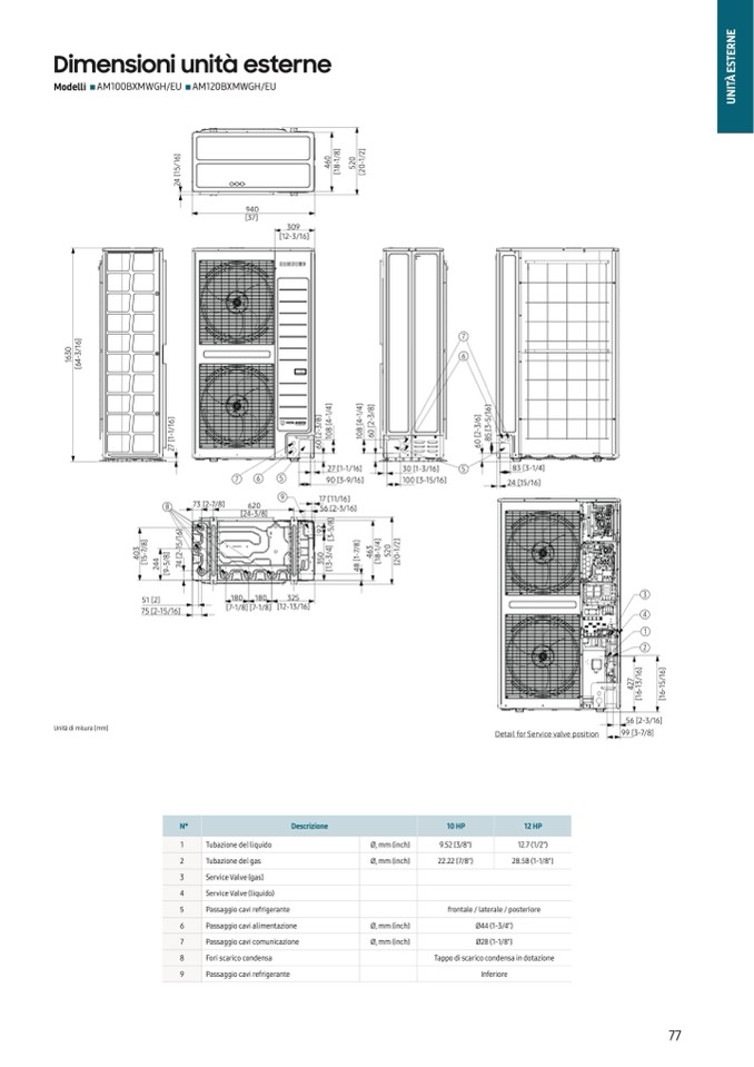
Dimensioni unità esterne
Modelli AM100BXMWGH/EU AM120BXMWGH/EU
Units : mm [inches]
E
N
R
E
T
S
E
A
̀
T
I
N
U
]
6
1
0
3
6
/
3
-
1
4
6
[
7
6
Unità di misura [mm]
Detail for Service valve position
51 [2]
75 [2-15/16]
180 180
325
[7-1/8] [7-1/8] [12-13/16]
3
4
1
2
]
6
1
]
6
1
7
2
4
/
3
1
-
/
5
1
-
6
1
[
6
1
[
56 [2-3/16]
99 [3-7/8]
Φ12.7 (Φ1/2)
Φ28.58 (Φ1-1/8)
]
]
8
/
]
2
/
6
1
/
0
6
4
1
-
8
0
2
5
1
-
0
5
1
[
1
[
2
[
4
2
940
[37]
NO
Name
1
Refrigerant liquid pipe
N°
2
Refrigerant gas pipe
1
Tubazione del liquido
3
Service Valve (Gas)
2
Tubazione del gas
4
Service Valve (Liquid)
3
Service Valve (gas)
5
Knockout hole for pipe intake
4
Service Valve (liquido)
6
Power wiring conduits
5
Passaggio cavi refrigerante
10 HP
Φ9.52 (Φ3/8)
10 HP
Φ22.22 (Φ7/8)
Description
12 HP
12.7 (1/2")
28.58 (1-1/8")
Front / Side / Rear
12 HP
7
Communicatio6 n wirPinasgsacgogino dcauvitaslimentazione
8
Drain holes 7
Passaggio cavi comunicazione
9
Knockout hole for pipe intake
8
Fori scarico condensa
9
Passaggio cavi refrigerante
frontale / laterale / posteriore
Φ44 (Φ1-3/4)
Ø44
Φ(1-238/4"()Φ1-1/8)
309
[12-3/16]
]
4
/
]
4
/
]
8
/
]
6
1
]
6
]
8
/
1
-
4
1
-
4
3
-
2
]
6
/
/
5
-
1
/
1
3
-
[
8
[
8
[
0
3
-
2
3
[
-
1
[
2
[
0
0
1
0
1
6
[
0
5
8
7
2
6
6
27 [1-1/16]
30 [1-3/16]
5
83 [3-1/4]
7
6
5
90 [3-9/16]
100 [3-15/16]
24 [15/16]
9
8
73 [2-7/8]
17 [11/16]
620
56 [2-3/16]
[24-3/8]
]
2
]
8
/
5
]
6
1
/
9
-
3
[
]
]
]
3
0
8
/
7
-
]
5
1
-
2
0
]
4
/
8
/
7
-
3
6
4
/
1
-
0
2
2
/
1
-
4
5
1
[
4
8
/
5
[
4
5
3
3
-
3
1
[
4
8
1
[
5
0
2
[
2
-
9
[
7
1
[
8
4
Descrizione
Ø, mm (inch)
Ø, mm (inch)
Ø, mm (inch)
Ø, mm (inch)
9.52 (3/8")
22.22 (7/8")
Connect wØi2t8h(1t-h1/e8"p) rovided drain plug.
Tappo di scarico condensa in dotazione
Bottom
Inferiore
77

