DIMENSIONAL
I
Linea Commerciale
SERIE P - UNITÀ ESTERN
E
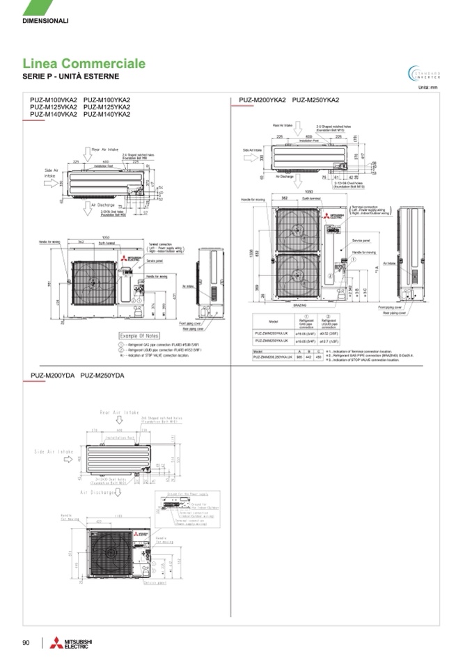
PUZ-M100VKA2 PUZ-M100YKA
2
PUZ-M100VKA2 PUZ-M100YKA2
PUZ-M100VKA2 PUZ-M100YKA
2
PUZ-M125VKA2 PUZ-M125YKA
2
PUZ-M125VKA2 PUZ-M125YKA2
PUZ-M125VKA2 PUZ-M125YKA
2
PUZ-M140VKA2 PUZ-M140YKA
2
PUZ-M140VKA2 PUZ-M140YKA2
PUZ-M140VKA2 PUZ-M140YKA
2
OUTDOOR UNIT
OUTDOOR UNI
T
PUZ-M200YDA PUZ-M250YDA
9
0
Unità: mm
Unit : mm
Unit : mm
Installation Feet
Installation Feet
PUZ-M200YKA2 PUZ-M250YKA2
PUZ-M200YKA2 PUZ-M250YKA
2
PUZ-M200YKA2 PUZ-M250YKA2
OUTDOOR UNIT
OUTDOOR UNIT
Rear Air Intak
e
Rear Air Intak
e
2-U Shaped notched hole
s
2-U Shaped notched hole
s
(foundation Bolt M10
)
(foundation Bolt M10)
60
0 60
0
225
225
225
22
5
Side Air Intak
e
Side Air Intak
e
4
0
3
3
0
4
0
3
3
0
6
1
42
3
7
0
2
8
(
1
9
)
42
3
7
0
2
8
(
1
9
)
4
1
7
4
1
7
56
40
0
53
5
6
40
0
5
3
2-12×36 Oval hole
s
2-12×36 Oval holes
(foundation Bolt M10)
(foundation Bolt M10
)
Handle for movin
g
Handle for movin
g
Terminal connectio
n
Terminal connectio
n
Left...Power supply wiring
Left...Power supply wirin
g
(
)
Right...Indoor/Outdoor wirin
g
(
)
Right...Indoor/Outdoor wirin
g
Air Discharg
e
Air Discharg
e
75
1050
105
0
75
6
1
36
2 36
2
Earth termina
l
Earth termina
l
1
3
3
8
3
6
9
6
3
2
1
3
3
8
2
6
3
6
9
6
3
2
Handle for moving
Handle for movin
g
Service panel
Service pane
l
Air Intake
Air Intak
e
*
1
A
*
1
A
1
1
2
2
2
3
4
2
2
3
4
2
3
B
3
B
3
C
3
C
2
6
BRAZIN
G
BRAZIN
G
Front piping cover
Front piping cover
Rear piping cove
r
Rear piping cover
1
1
2
2
Mode
l
Mode
l
Refrigerant
Refrigerant
Refrigeran
t
Refrigeran
t
GAS pip
e
GAS pipe
LIQUID pipe
LIQUID pipe
connection
connection
connection
connection
PUZ-ZM/M200YKA.UK
ø19.05 (3/4F)
PUZ-ZM/M200YKA.UK
ø19.05 (3/4F) ø9.52 (3/8F
)
ø9.52 (3/8F)
PUZ-ZM/M250YKA.U
K
PUZ-ZM/M250YKA.U
K
ø19.05 (3/4F) ø12.7 (1/2F)
ø19.05 (3/4F)
ø12.7 (1/2F)
Model
C
Model
C
A
A
B
B
PUZ-ZM/M200,250YKA.UK
PUZ-ZM/M200,250YKA.UK
985 985
442 450
442
45
0
1...Indication of Terminal connection location.
1...Indication of Terminal connection location.
2...Refrigerant GAS PIPE connection (BRAZING) O.Dø25.4
.
2...Refrigerant GAS PIPE connection (BRAZING) O.Dø25.4
.
3...Indication of STOP VALVE connection location
.
3...Indication of STOP VALVE connection location
.
MX
Z
M
MX
Z
M
M
MX
Z
O
U
O
Air in
Air i
22.3
Handl
e
Han
d
5
5
0
5
5
0
2
8
0
2
8
0
1
0
MXZ
MX
MXZ
M
MXZ
M
OU
O
6
1
6
.
6
3
4
1
6
.
6
Air in
A
i
D
3
6
0
3
6
0

