DIMENSIONAL
I
Linea Commerciale
SERIE P - UNITÀ ESTERN
E
Unità: mm
Unit : mm
Unit : mm
Unit : m
m
2
L
2
OUTDOOR UNI
T
OUTDOOR UNI
T
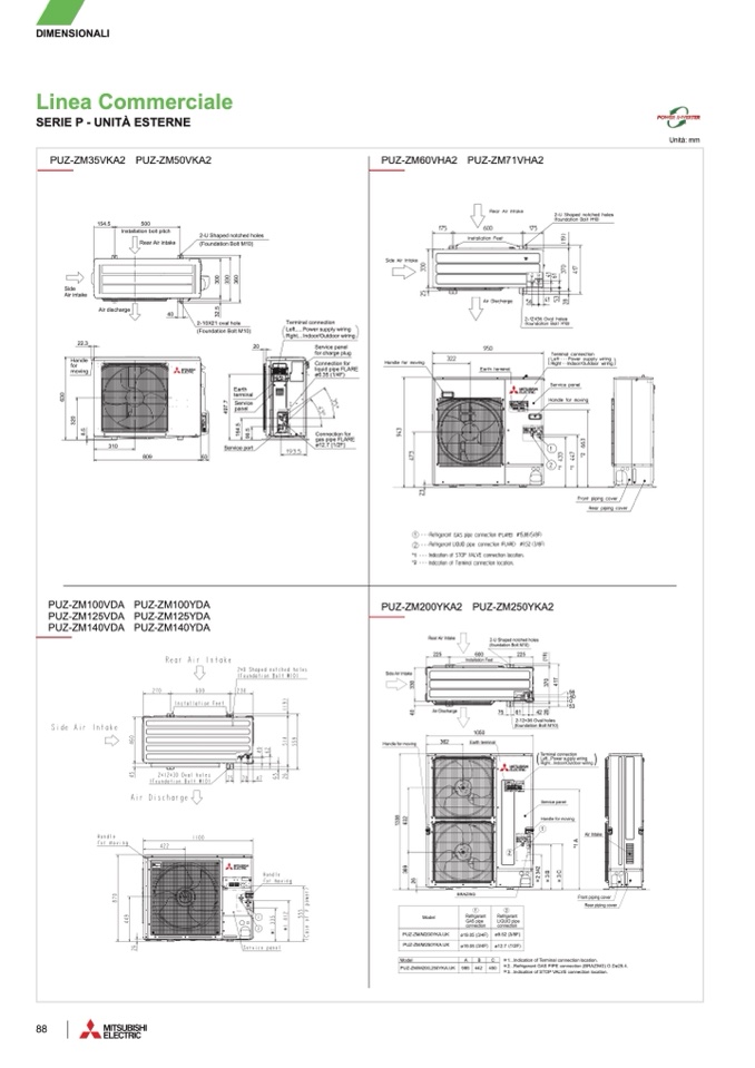
PUZ-ZM60VHA2 PUZ-ZM71VHA2
OUTDOOR UNIT
PUZ-ZM35VKA2 PUZ-ZM50VKA
2
PUZ-ZM35VKA2 PUZ-ZM50VKA
2
PUZ-ZM60VHA2 PUZ-ZM71VHA2
PUZ-ZM60VHA2 PUZ-ZM71VHA2
PUZ-ZM35VKA2 PUZ-ZM50VKA2
PUZ-ZM60VHA2 PUZ-ZM71VHA
2
OUTDOOR UNI
T
OUTDOOR UNI
T
PUZ-ZM35VKA2 PUZ-ZM50VKA
2
154.5
500
154.5
500
OUTDOOR UNI
T
Installation bolt pitch
Installation bolt pitch
Rear Air intake
Rear Air intake
2-U Shaped notched hole
s
2-U Shaped notched hole
s
(Foundation Bolt M10)
(Foundation Bolt M10)
154.5
500
Installation bolt pitc
h
3
0
0
3
0
0
Sid
e
Sid
e
Air intak
e
Air intak
e
Rear Air
intake
3
3
0
3
3
0
3
6
0
3
6
0
2-U Shaped notched hole
s
(Foundation Bolt M10
)
Air discharge
40
Air discharge
40
3
2
.
5
3
2
.
5
2-10X21 oval hol
e
2-10X21 oval hol
e
3
0
0
3
3
0
3
6
0
Sid
e
Air intake
(Foundation Bolt M10)
(Foundation Bolt M10)
Terminal connection
Terminal connection
Left.....Power supply wirin
g
Left.....Power supply wirin
g
Rght... Indoor/Outdoor wiring
Rght... Indoor/Outdoor wiring
22.3
22.3
Air discharge
40
3
2
.
5
20
20
2-10X21 oval hol
e
(Foundation Bolt M10
)
2
0
Service pane
l
Service pane
l
for charge plug
for charge plug
Terminal connection
Connection fo
r
Connection fo
r
Left.....Power supply wirin
g
liquid pipe FLAR
E
liquid pipe FLAR
E
Rght... Indoor/Outdoor wirin
g
ø6.35 (1/4F)
ø6.35 (1/4F)
Service pane
l
for charge plu
g
Eart
h
Eart
h
termina
l
termina
l
4
9
7
.
7
4
9
7
.
7
Service
Service
panel
panel
Connection fo
r
liquid pipe FLAR
E
ø6.35 (1/4F
)
Eart
h
terminal
1
6
4
.
5
1
6
4
.
5
9
9
.
5
9
9
.
5
4
9
7
.
7
Servic
e
pane
l
Service por
t
Service por
t
6
3
6
3
1
6
4
.
5
9
9
.
5
Service port
809
63
Unit : mm
6
3
0
6
3
0
Handle
Handle
for
for
movin
g
movin
g
3
2
0
3
2
0
22.3
Handle
fo
r
movin
g
6
3
0
8
.
5
8
.
5
310
310
3
2
0
8
.
5
809
809
310
Connection for
Connection for
gas pipe FLARE
gas pipe FLARE
ø12.7 (1/2F)
ø12.7 (1/2F)
Connection fo
r
gas pipe FLAR
E
ø12.7 (1/2F
)
*
2
*
2
*
1
*
1
*
2
*
1
*
1
*
1
*
1
transmission line)
necting line
)
2
Liquid pip
e
Ø6.3
5
Ø9.5
2
*1
*1
*2
*2
*
1
*
2
PUZ-ZM100VKA2 PUZ-ZM125VKA2 PUZ-ZM140VKA
2
PUZ-ZM100VKA2 PUZ-ZM125VKA2 PUZ-ZM140VKA
2
PUZ-ZM100VDA PUZ-ZM100YDA
PUZ-ZM100VKA2 PUZ-ZM125VKA2 PUZ-ZM140VKA2
PUZ-ZM100YKA2 PUZ-ZM125YKA2 PUZ-ZM140YKA
2
PUZ-ZM100YKA2 PUZ-ZM125YKA2 PUZ-ZM140YKA
2
PUZ-ZM125VDA PUZ-ZM125YDA
PUZ-ZM100YKA2 PUZ-ZM125YKA2 PUZ-ZM140YKA2
OUTDOOR UNI
T
OUTDOOR UNI
T
PUZ-ZM140VDA PUZ-ZM140YDA
OUTDOOR UNI
T
Installation Feet
Installation Feet
Installation Fee
t
PUZ-ZM200YKA2 PUHZ-ZM250YKA2
PUZ-ZM200YKA2 PUHZ-ZM250YKA2
PUZ-ZM200YKA2 PUHZ-ZM250YKA
2
PUZ-ZM200YKA2 PUZ-ZM250YKA2
OUTDOOR UNIT
OUTDOOR UNIT
OUTDOOR UNIT
Rear Air Intak
e
Rear Air Intak
e
Rear Air Intake
2-U Shaped notched hole
s
2-U Shaped notched hole
s
2-U Shaped notched holes
(foundation Bolt M10)
(foundation Bolt M10)
(foundation Bolt M10
)
225
22
5
225
22
5
60
0
60
0
60
0
225
225
Side Air Intake
Side Air Intak
e
Side Air Intak
e
4
0
3
3
0
4
0
3
3
0
4
0
3
3
0
3
7
0
61
61
42
42
2-12×36 Oval hole
s
2
8
(
1
9
)
2
8
(
1
9
)
4
1
7
4
1
7
4
2
2
8
(
1
9
)
4
1
7
3
7
0
3
7
0
(foundation Bolt M10
)
2-12×36 Oval hole
s
2-12×36 Oval hole
s
(foundation Bolt M10)
(foundation Bolt M10)
5
6
4
0
0
5
3
56
56
4
0
4
0
0 0
53
53
Terminal connectio
n
Left...Power supply wirin
g
(
)
Right...Indoor/Outdoor wirin
g
Terminal connectio
n
Terminal connectio
n
Left...Power supply wiring
Left...Power supply wiring
(
)
(
)
Right...Indoor/Outdoor wiring
Right...Indoor/Outdoor wiring
Air Discharg
e
Air Discharg
e
Air Discharg
e
7
5
7
5
7
5
105
0
6
1
36
2
105
0
105
0
Earth termina
l
Handle for movin
g
36
2
36
2
Handle for moving
Handle for moving
Earth termina
l
Earth termina
l
Service panel
Handle for moving
Service pane
l
Service pane
l
1
3
3
8
1
3
3
8
3
6
9
6
3
2
PUZ-ZM/M200YKA.UK
3
6
9
6
3
2
3
6
9
6
3
2
1
3
3
8
2
6
2
6
Model
2
2 2
2
3
4
2
3
B
3
C
1 1
1
Air Intake
Handle for moving
Handle for moving
*
1
A
*
1
A
*
1
A
Air
Air Intake
Intake
2
6
BRAZIN
G
1
Refrigerant
BRAZIN
G
BRAZIN
G
GAS pipe
connection
ø19.05 (3/4F)
2
Refrigerant
LIQUID pipe
connection
ø9.52 (3/8F)
PUZ-ZM/M250YKA.U
K
Model
Model
1 1
ø19.05 (3/4F)
Refrigerant
Refrigerant
2 2
ø12.7 (1/2F)
Refrigeran
t
Refrigeran
t
2
3
4
2
2
3
4
2
3
B
3
B
3
C
3
C
Front piping cove
r
Rear piping cover
Front piping cover
Front piping cover
Rear piping cove
r
Rear piping cove
r
GAS pip
e
GAS pip
e
LIQUID pipe
LIQUID pipe
connection
connection
Model
C
A
B
connection
connection
1...Indication of Terminal connection location.
PUZ-ZM/M200YKA.UK
PUZ-ZM/M200YKA.UK
PUZ-ZM/M200,250YKA.UK
ø19.05 (3/4F) ø9.52 (3/8F
)
ø19.05 (3/4F) ø9.52 (3/8F
)
985
442
45
0
2...Refrigerant GAS PIPE connection (BRAZING) O.Dø25.4.
3...Indication of STOP VALVE connection location.
PUZ-ZM/M250YKA.U
K
PUZ-ZM/M250YKA.U
K
ø19.05 (3/4F) ø12.7 (1/2F
)
ø19.05 (3/4F) ø12.7 (1/2F
)
Model
C
Model
C
A A
B B
PUZ-ZM/M200,250YKA.UK
PUZ-ZM/M200,250YKA.UK
985
985
442 450
442 450
1...Indication of Terminal connection location
.
1...Indication of Terminal connection location
.
2...Refrigerant GAS PIPE connection (BRAZING) O.Dø25.4
.
2...Refrigerant GAS PIPE connection (BRAZING) O.Dø25.4
.
3...Indication of STOP VALVE connection location
.
3...Indication of STOP VALVE connection location
.
88

